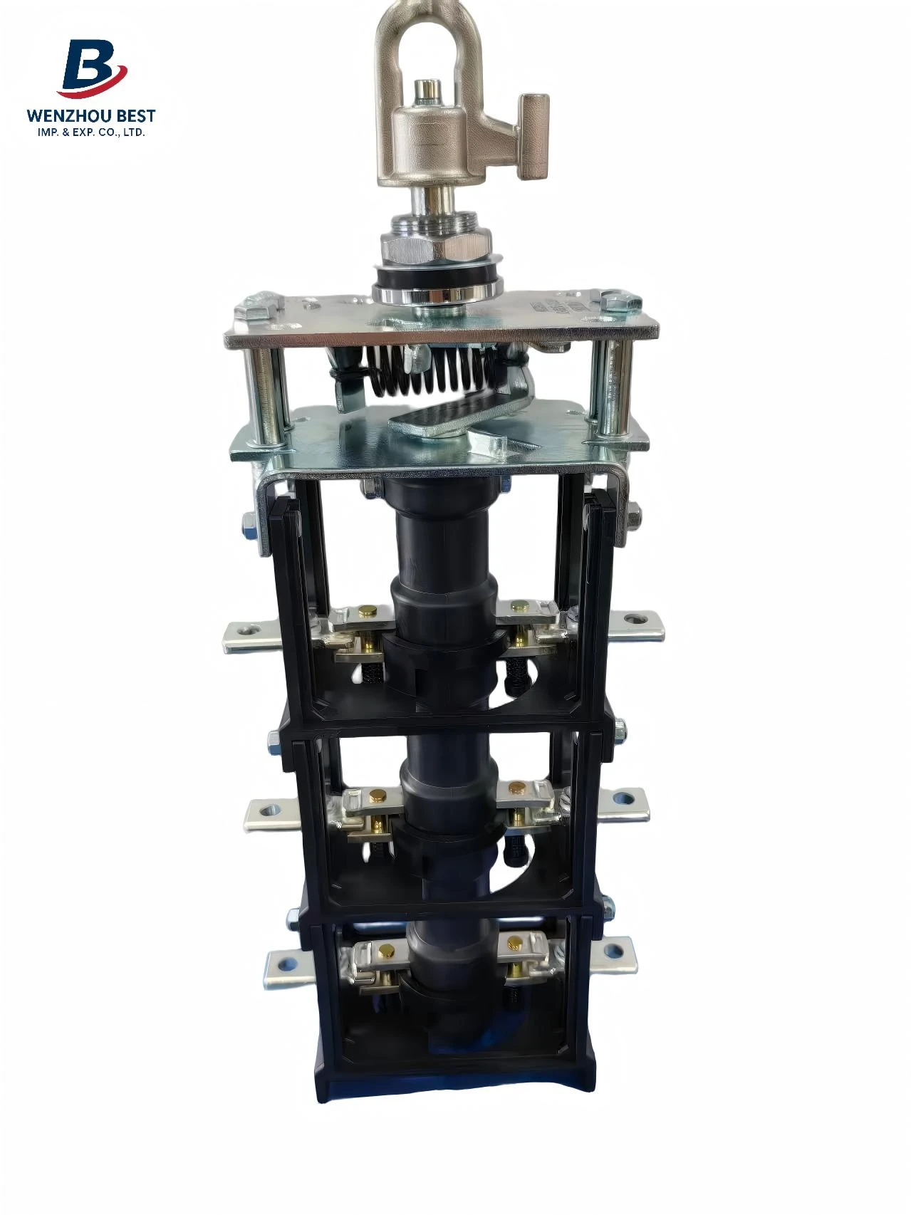
What Is a 10–35kV Voltage Transformer?
A 10–35kV voltage transformer is a type of medium-voltage instrument transformer designed to transform a high primary voltage into a lower secondary voltage.
For example, a VT may have a primary voltage of:10kV, 11kV, 12kV, 15kV, 20kV, 24kV, 34.5kV, 35kV
The secondary voltage is normally much lower, commonly around 100V, 100/√3V, 110V , 115/√3 , 115V or 120V, depending on the system, standard and application.
The basic relationship can be expressed as:
Primary Voltage / Secondary Voltage = Voltage Ratio
For example:
10,000V / 100V = 100:1 or 34,500V / 115V = 300:1
The actual ratio must always be selected according to the system voltage and the requirements of the metering or protection equipment.
How Does a Voltage Transformer Work?
A conventional electromagnetic VT works according to the same basic electromagnetic induction principle as a power transformer.
The primary winding is connected to the medium-voltage circuit. When AC voltage is applied, it produces magnetic flux in the iron core. This magnetic flux induces a proportional voltage in the secondary winding.
The number of turns in the primary and secondary windings determines the voltage ratio.
For example:
Primary winding → Magnetic core → Secondary winding
The primary winding is connected to the 10–35kV system, while the secondary winding provides a much lower voltage signal to measuring or protection equipment.
The important difference is that a VT is designed primarily for voltage measurement and signal accuracy, rather than supplying large amounts of electrical power.
Why Are Voltage Transformers Used in Medium-Voltage Systems?
Directly connecting a 10–35kV circuit to a conventional meter or protection relay is obviously not practical.
A voltage transformer provides three important functions.
1. Voltage Reduction
The VT converts the high primary voltage into a low secondary voltage suitable for meters, relays and control devices.
2. Electrical Isolation
The secondary measuring and protection circuits are electrically isolated from the medium-voltage primary system.
This helps improve safety and allows standard low-voltage measuring and control equipment to be used.
3. Accurate Voltage Measurement
A properly selected VT reproduces the primary voltage with a controlled ratio error and phase-angle error.
This is particularly important for:
*Energy metering
*Voltage measurement
*Protective relaying
*Synchronization
*Power quality monitoring
*Control systems
Main Applications of 10–35kV Voltage Transformers
10–35kV VTs can be found in many medium-voltage installations.
1. Medium-Voltage Switchgear
VTs are frequently installed in MV switchgear to provide voltage signals for protection relays, meters and control systems.
Typical applications include:
Metal-clad switchgear
Metal-enclosed switchgear
Ring main units
MV distribution panels
Indoor and outdoor switchgear
2. Substations
Voltage transformers are commonly used in distribution substations for monitoring the voltage of incoming or outgoing feeders.
The secondary signal can be connected to:
Digital meters
Protection relays
SCADA systems
Monitoring devices
Control systems
3. Energy Metering
For electricity metering, the VT provides a reduced voltage proportional to the primary system voltage.
The VT is often used together with a current transformer (CT).
The CT provides the current signal, while the VT provides the voltage signal.
Together, they allow the metering system to calculate:
Voltage
Current
Active power
Reactive power
Apparent power
Power factor
Energy consumptio
4. Protective Relaying
Protection relays need voltage information to determine abnormal conditions in the electrical network.
VT signals may be used for:
Overvoltage protection
Undervoltage protection
Directional protection
Distance protection
Synchronizing
Ground-fault protection
Busbar protection
The quality of the voltage signal can therefore affect the performance of the protection system.
5. Auxiliary and Control Power
In some medium-voltage applications, a VT may also be specified to provide a controlled secondary voltage for auxiliary or control circuits.
This is different from a VT used purely for measurement.
When a VT is intended to supply auxiliary power, the required secondary voltage, VA rating and thermal capability need to be considered carefully.
This is especially important when a customer describes the VT as a CPT (Control Power Transformer).
Common Types of 10–35kV Voltage Transformers
Medium-voltage VTs can be classified in several ways.
Single-Phase Voltage Transformer
A single-phase VT is commonly used where each phase needs to be measured individually.
Three single-phase VTs can also be connected together to form a three-phase voltage measurement system.
Three-Phase Voltage Transformer
A three-phase VT combines the three phases into one assembly.
Depending on the application, the primary and secondary windings may use different connection arrangements.
Common configurations include:
Star-Star
Delta-Delta
Open Delta
Broken Delta
The appropriate connection depends on the system grounding arrangement and protection requirements.
For example, broken-delta secondary connections can be used for detecting zero-sequence voltage and ground faults in certain medium-voltage systems.
What Should Be Confirmed Before Ordering a 10–35kV VT?
For a customized voltage transformer, we recommend confirming at least the following information:
System voltage
Rated primary voltage
Secondary voltage
Voltage ratio
Frequency
Accuracy class
Rated burden / VA
Metering or protection application
Insulation level
Voltage factor
Single-phase or three-phase
Primary and secondary connection
Indoor or outdoor installation
Dry-type or oil-immersed construction
Applicable standard
Mounting and terminal requirements
For projects using North American standards, IEEE requirements should be specified alongside the project voltage, accuracy and burden requirements. For IEC-based projects, IEC 61869 requirements should be considered.
For other relevent questions please contact Wenzhou Best Imp. &Exp. Co., Ltd engineer team to get professional information.
FAQ
Q1. What is the difference between VT and PT?
VT and PT generally refer to the same type of instrument transformer. VT means Voltage Transformer, while PT means Potential Transformer.