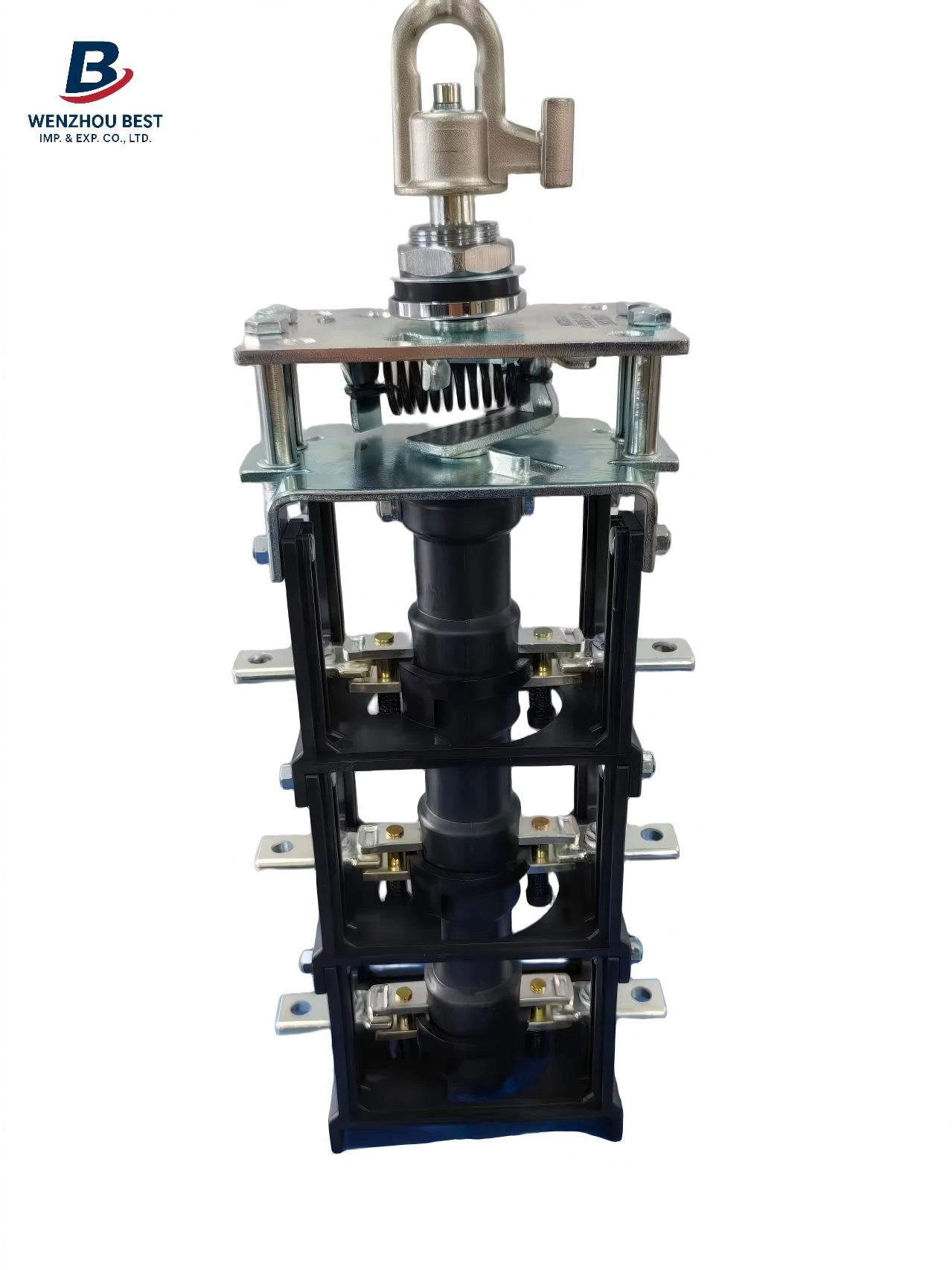
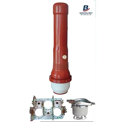
The wiring method for current transformers (CTs) is critical in power measurement and protection circuits; its correctness directly impacts metering accuracy and system safety. Typically, the primary side of a current transformer is connected in series with the circuit under measurement-that is, inserted into the load circuit-ensuring that the entire current being measured flows through the primary winding. The secondary side, conversely, is connected to measuring instruments or protective relay devices to form a closed loop, thereby outputting a standard low-current signal proportional to the primary current. It is imperative to note that the secondary side must never be left open-circuited during operation; doing so would generate dangerously high voltages, posing a significant safety hazard.
During the actual wiring process, it is essential to strictly distinguish the polarity terminals of the current transformer; typically, P1 and P2 designate the primary side, while S1 and S2 designate the secondary side. When wiring, the direction of current flow must be consistent: the primary terminal P1 should be connected toward the power source side, and P2 toward the load side, while the secondary terminal S1 should correspond to the direction flowing toward the measuring instrument, thereby ensuring correct measurement phasing. If the polarity is reversed, it may lead to deviations in instrument readings or erroneous tripping of protective devices; consequently, a polarity verification procedure is typically performed after installation.
Furthermore, it is necessary to standardize the wiring configuration to prevent phase sequence confusion. The secondary circuit should generally be reliably grounded-typically at a single point on the secondary side-to enhance the system's immunity to interference and ensure personnel safety. When performing maintenance or removal procedures, the secondary side must first be short-circuited before proceeding with any operations, in order to prevent the generation of induced high voltages. A rational and standardized wiring approach not only improves measurement accuracy but also effectively safeguards the stable operation of the power system.